Simulators — /simulators
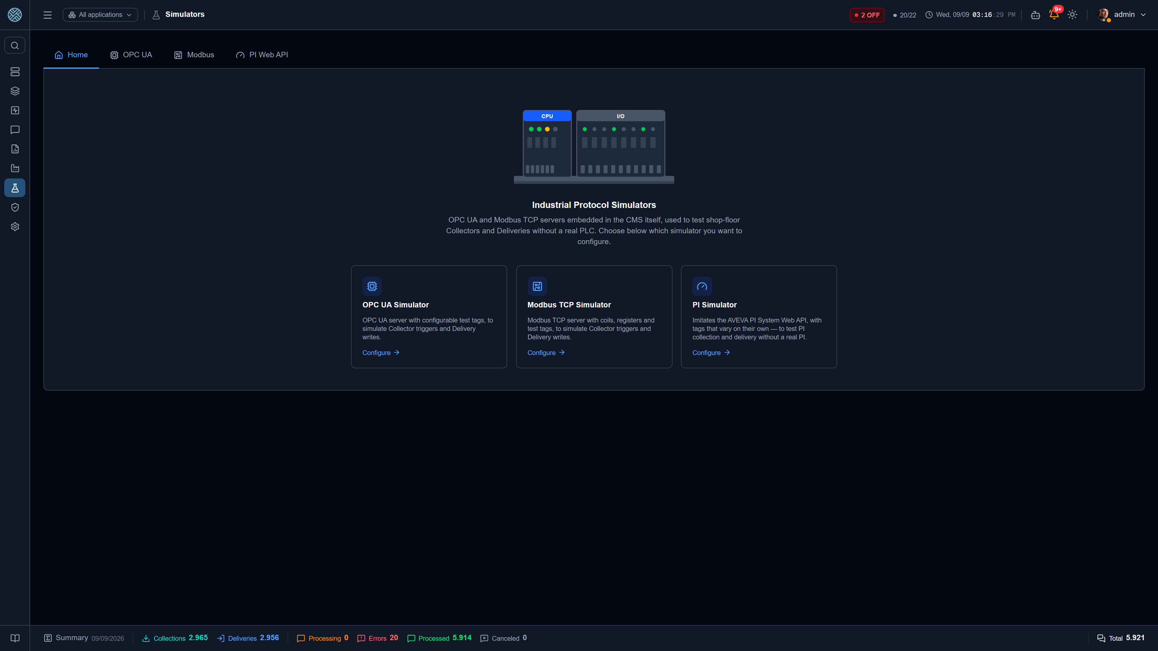
Configuring a shop floor integration usually hits a scheduling problem: the PLC is on the production line, the PI System belongs to another team, and nobody clears testing on equipment during production hours. The CMS solves this by bringing the servers inside itself.
It moved in the menu. Since September 2026 the Simulators live under Integration Lab, no longer under Integration Config (formerly Shop Floor). That is where an integration gets exercised, next to the Test Bench and the Test Plans — the simulator fakes the source, the Test Bench fires the stimulus, and testing a field Collection means using both together.
There are three, in separate tabs:
| Simulator | Imitates | Runs on |
|---|---|---|
| OPC UA Simulator | An OPC UA server (PLC, gateway) | Its own TCP port, 4841 by default |
| Modbus Simulator | A Modbus TCP slave | Its own TCP port, 5020 by default |
| PI Simulator | AVEVA PI System’s PI Web API | Inside the API itself, no new port |
They are used to:
- validate a Collection or Delivery configuration before having access to the equipment;
- reproduce an error scenario in a test environment, as many times as needed;
- demonstrate the full flow without depending on the plant;
- train operators without the risk of writing to real equipment.
No simulator is enabled by default. All three are QA and demonstration features — turn one on when you need it and off afterwards. A simulator left running in a production environment is one more open door.
What all three share
The External Connection appears on its own
Enabling a simulator makes the CMS create and maintain the matching External Connection — “OPC Simulator (internal)”, “Modbus Simulator (internal)”, “PI Simulator (internal)”. It shows up normally in External Connections and can be picked in an Application, a Collection or a Delivery like any other. There is no address to type, and no risk of typing it wrong.
Disabling the simulator does not delete the connection: it simply stops responding.
Profiles: saving whole scenarios
All three simulators work with profiles — named snapshots of the tag set. Instead of re-entering tags one by one for each test, you save “Press 3”, “North Plant”, “Failure scenario” and switch between them.
| Action | What it does |
|---|---|
| Save current configuration | Creates a profile with the tags currently in the simulator |
| Apply | Replaces all current tags with the profile’s |
| Overwrite | Updates the profile with the current tags |
| Delete | Removes the profile; the simulator’s active tags are untouched |
Apply and overwrite ask for confirmation, because both swap an entire tag set at once.
Profiles are part of the configuration import/export in the Danger Zone — each simulator with its own domain. That is how a scenario built on the implementer’s machine ends up in the demo environment.
Any change restarts the server
Saving a tag, applying a profile or changing the port rebuilds the server from scratch. That is deliberate: touching the address space “live” would be more complex and more prone to inconsistent state — and this is not a production path. Changes are grouped in a short window, so saving five tags in a row causes one restart, not five.
OPC UA Simulator
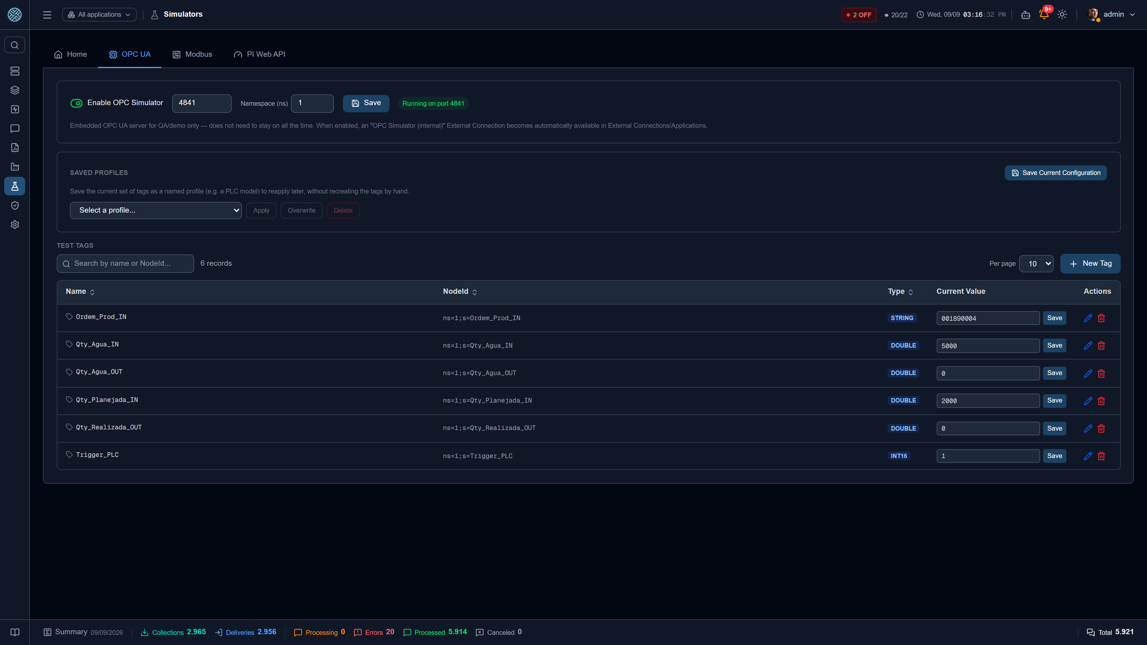
A full OPC UA server, served by cms-api itself. It exposes one variable per registered tag.
Configuration
| Field | Role |
|---|---|
| Enable | Starts/stops the server |
| Port | 4841 by default — the endpoint is opc.tcp://localhost:4841/opc-simulator |
| Namespace (ns) | Namespace index of the created tags. It goes into the NodeId |
The footer shows the real state: Running on port N or Stopped, and the error when the port is already taken.
The server listens on 127.0.0.1 only, inside cms-api: CMS’s own Collections and Deliveries reach
it, an outside client (UaExpert, another server on the network) does not. That is on purpose — the
simulator is anonymous and its tags are writable.
Test tags
Each tag has a name, a NodeId, a data type and a current value:
- Types —
BOOLEAN,INT16,INT32,FLOAT,DOUBLE,STRING. - NodeId — follows the
ns={ns};s=TagNameformat, suggested automatically from the name. - Current value — editable in the list itself, with a button that writes it immediately. On a
BOOLEANtag that button is called Trigger; on other types, Save.
That button is what makes the simulator genuinely useful: an OPC_UA_TRIGGER Collection subscribes
to the tag, and you fire it whenever you want, without waiting for a machine cycle.
The simulator also accepts writes. An OPC_UA_WRITE Delivery pointed at it writes to the tags, and
the list shows the new value — the most direct way to check whether the Write Tags mapping is
correct. See OPC UA.
Modbus Simulator
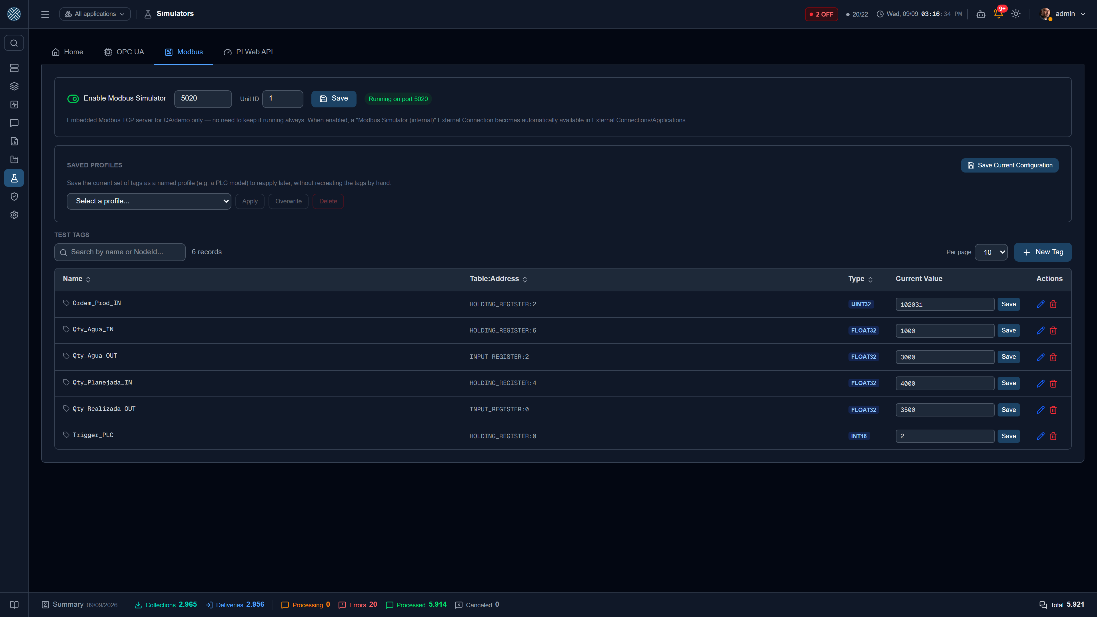
An embedded Modbus TCP slave. Unlike OPC UA, Modbus has no object model: the protocol operates over four raw register arrays, addressed by number.
| Field | Role |
|---|---|
| Enable | Starts/stops the server |
| Port | 5020 by default (avoids the privileged port 502) |
| Unit ID | Slave identifier, as on real equipment |
The four tables
| Table | Nature | Writable by the master |
|---|---|---|
| Coil | Bit | Yes |
| Discrete Input | Bit | No (read only) |
| Holding Register | 16 bits | Yes |
| Input Register | 16 bits | No (read only) |
A tag’s address is written as Table:Address — for example HOLDING_REGISTER:40.
Data types and word order
Since a Modbus register holds 16 bits, larger values take two consecutive registers. Tags declare:
- Type —
BOOLEAN,INT16,UINT16,INT32,UINT32,FLOAT32. - Word order —
BIG_ENDIANorLITTLE_ENDIAN, for the 32-bit types.
Wrong word order is the classic Modbus mistake: the value arrives, no error is raised, and it is
nonsense (a FLOAT32 of 25.3 showing up as 4.6e-41). The simulator is the cheap place to find out
which of the two your equipment uses.
The simulator’s tag layer is a convenience of the screen — name and type on top of the raw registers. What the master sees are the registers.
PI Simulator
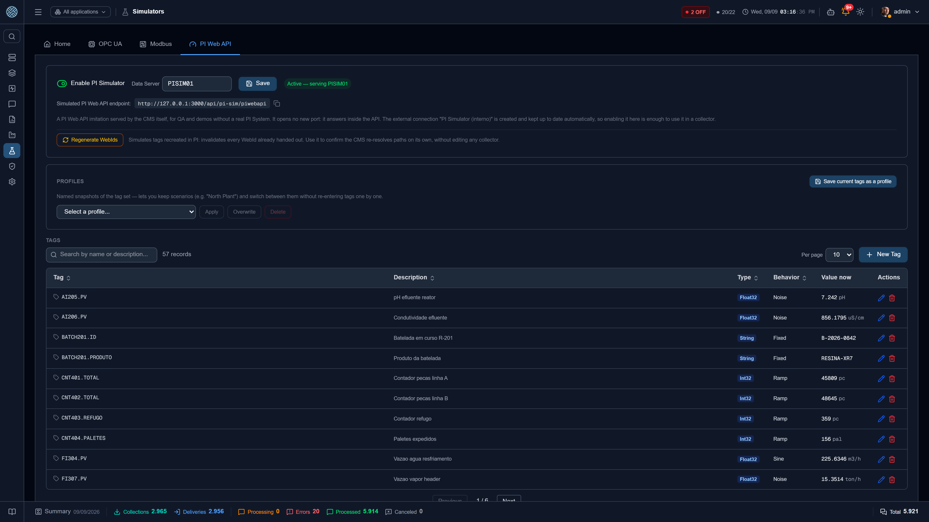
An imitation of AVEVA PI System’s (formerly OSIsoft) PI Web API. It is the only one of the three
that does not open a new port: the PI Web API is REST, so the simulator is an endpoint inside the
CMS API itself, at /api/pi-sim/piwebapi. Only CMS itself reaches it: at the edge (nginx) the route
answers 404, because the simulator accepts reads and writes without authentication.
| Field | Role |
|---|---|
| Enable | Starts accepting requests on the simulated endpoint |
| Data Server | Name of the simulated PI server (PISIM01 by default) |
| Seed | Number that feeds WebId generation — see below |
Tags that vary on their own
This is the central difference from the other two simulators. A PI System stores time series: asking “what is the value now” is less interesting than asking “how did it behave in the last hour”. So each tag has a behaviour, and the value is computed as a function of time:
| Behaviour | What it does |
|---|---|
| Sine | Oscillates smoothly between base ± amplitude, one cycle per period |
| Ramp | Rises linearly from (base − amplitude) to (base + amplitude) and restarts |
| Square wave | Alternates between the two extremes every half period |
| Noise | Smooth pseudo-random variation within the range — looks like a real process signal |
| Fixed | Keeps the last written value |
The parameters are base value, amplitude and period (s). Each tag also has a name,
description, unit and point type (Float32, Float64, Int32, Digital, String).
Fixed is the behaviour for testing Delivery. In the other options the value is a function of
time, so whatever a Delivery writes would immediately be overwritten by the generator. With
FIXED, what the Delivery writes is what the read returns.
Because the value is computed rather than stored, history queries work for any interval — including before the simulator existed. There is no series to populate.
Regenerate WebIds
In PI, every object is addressed by an opaque WebId, which the CMS resolves from the tag path and caches. When tags are recreated in PI, or the server is migrated, those WebIds stop being valid and the client has to re-resolve the paths on its own.
The Regenerate WebIds button causes exactly that: it invalidates every WebId already handed out. It proves the CMS recovers without anyone editing a single Collection — a scenario that on a real PI would be expensive and risky to reproduce.
Fidelity to the real product
The simulator reproduces the PI Web API REST contract, including details that usually catch integrators out:
- it requires the
X-Requested-Withheader, like the real PI, which returns 401 without it; - a query by
pathreturns the object directly, not a collection; - a stale WebId answers 404, not a generic error;
- history responses are capped at 5,000 samples.
What it does not reproduce is authentication: it accepts any credential, or none — like an open lab PI. See PI Web API.
Writing to equipment: the permission gate
Writing to an OPC UA tag or a Modbus register changes the state of real equipment. That is why
OPC_UA_WRITE and MODBUS_WRITE Deliveries accept a write permission tag on the equipment
itself: the CMS subscribes to that tag and only writes while it holds the expected value.
It is the PLC, not the CMS, that decides when to accept a write — the only correct order for that decision. Without the tag configured, the Delivery writes whenever it receives a message.
Configure the gate in production environments. Without it, a malformed payload coming from a corporate system reaches the equipment.
Failing without being able to ask
A Delivery with a gate configured whose tag subscription is not up answers no — never “there is no restriction”. The difference looks subtle and is not: until August 2026 the OPC UA gate answered by reading whether the session existed, and “gate configured, but I could not connect” arrived there looking exactly like “this Delivery has no gate”. The outcome was the worst possible one — failing to check whether the PLC could accept a write released the write to the PLC. Today both gates, OPC UA and Modbus, fail closed.
The gate connection also retries on its own, with a growing wait from 2s to 20s, and a drop fires
CONEXAO_OPCUA_PERDIDA or CONEXAO_MODBUS_PERDIDA. Before, a failure on the first attempt left the
Delivery without a gate until someone restarted the API.
A drop only becomes a log line and an alert after 10 seconds down, and it is one line per drop, not one per attempt. The built-in simulators open their port a few seconds after the gates try their first connection, in the same process: one ERROR per startup, over an outage that resolves itself, is precisely how an operator is taught to ignore gate errors.